Chapter 11 Manual Transmission
Introduction
In our discussions of networking, DNS, HTTP, and email so far, we’ve used words like “request” and “response” to describe something that travels through the Internet. That something could be the CNN home page, a query for the IP address of reddit.com, or the third email in my inbox. However, we’ve kinda taken for granted that a request knows where it came from and knows where it’s going, as well as exactly what information goes into a request. In our final foray into the study of the Internet, let’s peel back this last final layer and take a look at exactly what’s being sent from router to router on the information superhighway.
TCP Fundamentals
The delivery of information through the Internet is handled by—you guessed it—more protocols! This time, we’ll be looking at a suite of protocols called TCP/IP; indeed, for something as important as sending information through the net, we’ll need more than just one protocol! First, let’s talk about TCP, the Transmission Control Protocol. We’ve seen how an application like Google Chrome can request a resource from a web server using HTTP, and now TCP is one of the protocols responsible from getting that textual HTTP request from your computer to a server. So, the browser will construct an HTTP request, and then that HTTP request will be transferred using TCP.
TCP is connection-oriented, which means that two machines communicating using TCP will first establish a connection with each other by sending a nice greeting. Only once the two devices have exchanged pleasantries will they begin sending messages over that connection. With TCP, only the two ends of the communication, in our case the client and the server, need to worry about remembering anything related to the connection. The rest of the devices on the network, like the routers connecting the client and server, are stateless, which means they never need to store any data relating to the TCP connection.
TCP transmits messages by breaking them up into smaller units called segments. So, if a web server needs to send a client a large HTTP response, TCP will handle the task of breaking that large message into smaller, more manageable chunks that will be sent over a network. Each of these segments looks like this:
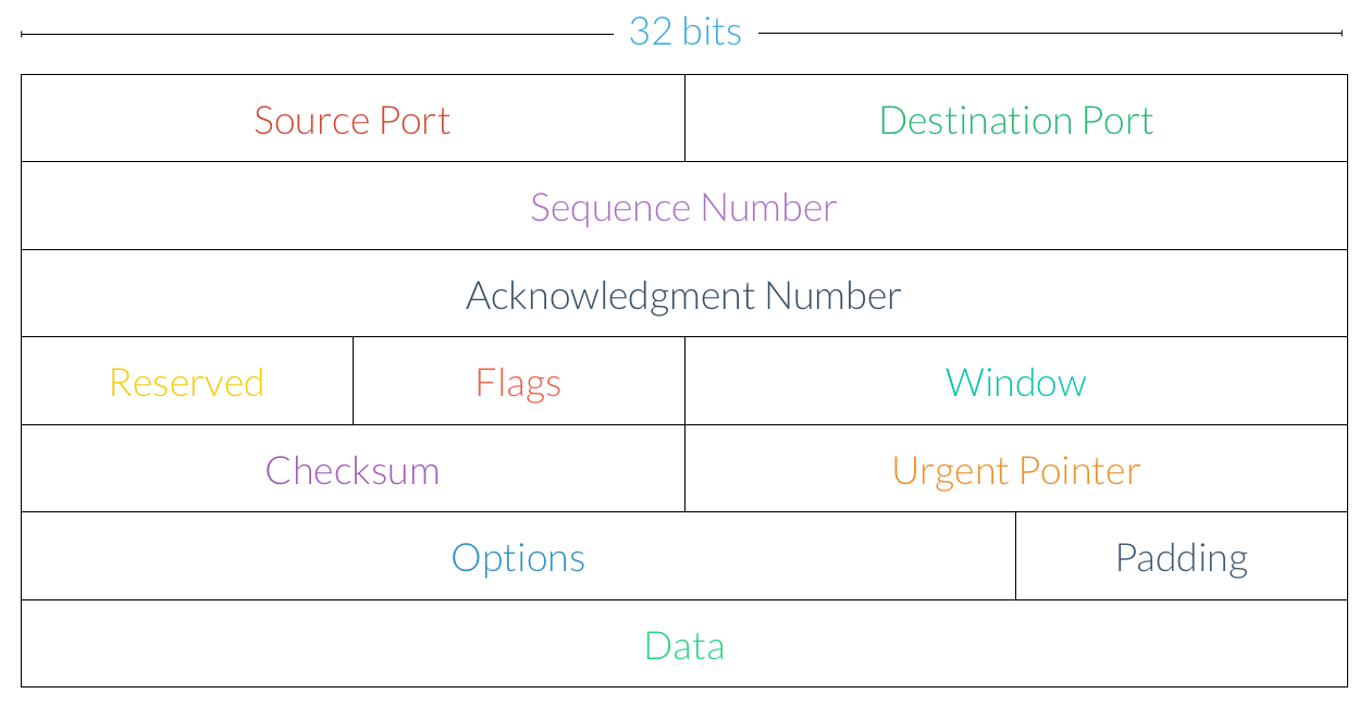
Let’s walk through some of these components:
-
Source Port. A request’s source port provides some additional information about where the address came from. For example, in the context of NAT, the source port is used to identify a machine with a private IP address.
-
Destination Port. The destination port provides some additional information about where the request is going to. Recall that the email protocols we saw earlier—SMTP, POP3, and IMAP—communicated over different ports.
-
Sequence Number. The sequence number is used to ensure segments are delivered in the correct order. More on these in a bit!
-
Acknowledgment Number. Acknowledgments are used to ensure segments reach their destinations. More on these in a bit as well!
-
Flags. As we’ll see shortly, some TCP segments, like those that open or close a connection, are special. The flags section is used to supply some additional information about the type of the segment.
-
Window. The window indicates how many segments will be sent from a client at once, which can be used to limit congestion on the network.
-
Checksum. The checksum field is used for error checking and validation.
-
Data. The actual data to be transmitted over the network is found at the end of the segment. The data section is also referred to as the body or payload.
If we’re using TCP to transmit an HTTP request, for example, then the actual text of the request will be found in the segment’s data section. Hmm, but it looks like TCP segments aren’t concerned with IP addresses at all, so that much must be handled by that other protocol, IP (whatever that is).
When sending a request to a web page, we want to adhere to something called reliable data transfer, which essentially ensures that a message sent by one party is correctly received by the other party. Not only do we expect all of the segments transferred from the client to make it all the way to the server (and vice-versa), but we also want to make sure they’re transferred in the right order. Remember, a single HTTP response will be broken up into multiple TCP segments, and those segments are what will actually be sent over the network independently. Of course, when we head to CNN.com, we don’t expect the page to be missing any pictures or have words appearing out of order! TCP is designed with exactly these goals in mind. If the network loses track of some parts of a message or delivers them out of order (which actually is exactly what will happen much of the time), then TCP will take care of ensuring everything gets delivered the way it was meant to be. So, other protocols like HTTP don’t need to worry about re-ordering segments or checking for missing data, since the underlying TCP protocol has already taken care of that.
Sending a TCP Segment
Let’s take a look at the process of sending a message over TCP. Each TCP segment has a field called a sequence number, which allows TCP segments to have an ordering associated with them (check out the diagram in the last section if you haven’t already). If a client wants to send a message that’s 5,000 bytes long and the maximum size of a TCP segment is 1,000 bytes (though that exact number varies), then five TCP segments will be created: the first 1,000 bytes could have a sequence number of 0, the second 1,000 bytes could have a sequence number of 1,000, the third 1,000 bytes could have a sequence number of 2,000, and so on. So, even if the server receives these segments out of order, then TCP can use the sequence numbers on each segment to reconstruct the original message.
Looks like sequence numbers handle the problem of segments being delivered out of order, but what about ensuring that all TCP segments successfully reach their destination? To solve this issue, have the receiver will send acknowledgment messages, or ACKs for short, that let the sender know that each segment has been received. For each TCP segment that is delivered successfully, the receiver will transmit a message to the sender saying “I got that segment, go ahead and send another one.” So, once a sender receives an ACK from the receiver, it knows that the segment has been successfully delivered! If an ACK is not received, on the other hand, then the sender can’t be sure that the receiver has indeed received the segment, so it may need to send that same segment again. ACKs are kinda like those thank you notes your parents probably made you send to your relatives whenever you got a present; they let the sender know that you’ve received the package and are looking forward to wearing that new sweater.
Okay, so each time a segment is sent via TCP, the sender expects to receive an ACK from the receiver. Each time the sender transmits a new segment, it starts a new countdown timer, much like you’d set an oven timer when baking cookies. The timer is set to an estimate of how long it should take for the segment to be delivered and for the receiver’s ACK to reach the sender. If the timer goes off before the sender receives an ACK, then a timeout occurs, and the sender will have to assume that the message was lost in the Internet abyss. When this happens, the sender will re-transmit the lost segment, this time with a new, adjusted timer. For example, the sender might want to double the timer’s value, in the event the network has slowed down a bit. On the flip side, if the receiver is sending ACKs much faster than the sender originally anticipated, then the sender might want to decrease its timer value in order to keep up.
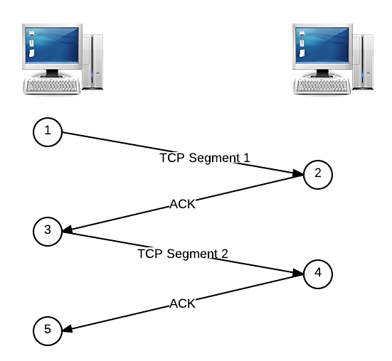
Below is a basic example of sending a message using TCP. The sender’s message has been broken up into two TCP segments, sent one after another, and the receiver acknowledges when it has received each segment by replying with an ACK. We’ll read this diagram from top to bottom, and the numbers outlined in circles represent chronological steps in the transmission process.
TCP Handshake
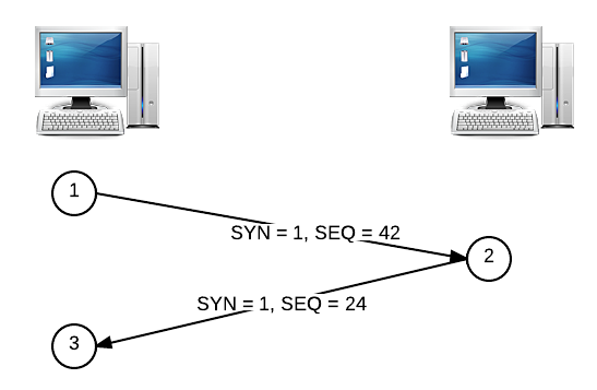
Let’s come back to those sequence numbers again. The first messages exchanged in a TCP connection, as we mentioned earlier, are special. When a client seeks to establish a TCP connection with a server, it will send a TCP segment with a special bit called the SYN, or synchronize field. The client will also pick a sequence number at random (for security reasons) and put it in the segment’s sequence number field. Let’s say that the client picks 42 as the sequence number for the SYN segment. The server’s ACK to a SYN segment is called a SYNACK, where the server similarly picks a sequence number to start off with (let’s say 24). This process is called a handshake and looks something like this:
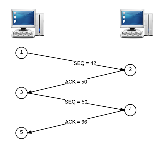
Now that sequence numbers have been set up by the handshake, they can be used in combination with ACKs to make sure all segments are delivered to the receiver in the correct order. We won’t worry too much about the sequence numbers on ACK segments coming from the receiver, though. Each ACK also has a special number that tells the sender which packets have been delivered to the receiver so far. Let’s say that an 8-byte segment is sent with a sequence number of 42. When this segment is received, the receiver will respond with an ACK numbered 50, which is simply 42 + 8 (or the sequence number + the size of the segment). When the sender receives this ACK, it knows that the next segment to be sent should have a sequence number of 50, since the receiver has acknowledged that it has received all data up to sequence number 50. If the next segment to be sent is 16 bytes in size, the receiver will reply with an ACK numbered 66 upon a successful delivery, which tells the sender that the next segment should start with a sequence number of 66.
Here’s an illustrated version of that story. To recap, the client on the left is sending two segments to the server on the right. The first segment is 8 bytes in size, the second segment is 16 bytes in size, and the handshake process has already established an initial sequence number of 42.
Dropped Segments
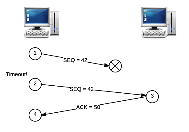
Alright, but what happens if some segments are never delivered? Suppose instead that the segment with the sequence number of 42 gets lost in the Internet ether, so the receiver never receives it. In this case, the receiver will not send an ACK, since the segment was not delivered. Eventually, the sender’s timer is going to go off, which signals that the same segment should be re-sent. Let’s illustrate this story, too. The segment numbered 42 is lost, so the client will try again after a timeout.
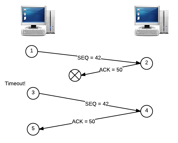
Okay, but what if it’s the ACK that gets dropped, and not the original segment? If this happens, then we have essentially the same scenario as above, and the segment must be re-sent in the same way:
Both of these examples assume that the sender will only try to send one segment at a time, waiting for an ACK before moving on. However, this isn’t really a very efficient way of sending a messages. We saw earlier that parallelism can be used to more efficiently solve a problem, so let’s apply the same principle here. Instead of sending segments in serial, one after the other, let’s send a couple segments in parallel, at the same time. Now, the client will be looking for a pair of ACKs from the server instead of just one. But, since either of these segments and either of these ACKs could end up being dropped by the network, we need some way of figuring out exactly what happened, so we don’t needlessly re-transmit segments!
To solve this problem, the receiver will send an ACK with a number that represents the total amount of data it has received in order. Let’s say that we send two segments at once: one has a sequence number of 42 (and is 8 bytes), and the other has a sequence number of 50 (and is 16 bytes). If only the second segment is delivered, then the receiver will reply with an ACK numbered 42, not 66. When the sender gets this ACK, it knows that the segment numbered 42 hasn’t been received yet, and it has no idea what happened to the segment numbered 50. But, the sender doesn’t really care about that second segment yet, since it’s important that all segments are received in the correct order. So, the sender will go ahead and re-send the segment numbered 42, since that’s what the ACK said to do. Now, the receiver can reply with an ACK of 66, since the segment with sequence number 50 has already been received! This might come as a pleasant surprise to the sender, since it had no idea whether or not segment 50 was delivered successfully. Here’s a picture for this story:
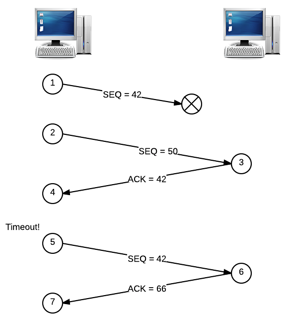
A sending client has a sliding window that determines how many packets will be sent by at once. Here, we have a window size of two, since the sender transmitted two segments before receiving any ACKs. Increasing the window will increase the traffic over the network, since more segments will be sent at once. So, adjusting the window can help prevent congestion on the network, since too many segments might overwhelm the network.
IP Fundamentals
Let’s take a break from TCP and take a look at the other half of the TCP/IP protocol pair: IP. IP is actually even more fundamental than TCP, since we haven’t yet talked about where routers come into play in the process of sending information through a network. IP stands for Internet Protocol, and we’ve actually already seen some of the important features of IP. We know that each device on a network has an associated IP address, which is a unique number on the network. When a computer wants to send a message to another device, it uses its IP address to identify it. However, if two computers aren’t directly connected on the network, then this message will have to travel through one or more routers in order to eventually reach its destination. As we saw before, not every router on the Internet knows where every other device is. Instead, each router has a routing table that describes where the best place to send the message next would be, so it can reach its destination as quickly as possible. Since we know how TCP works now, let’s can think about these “messages” as TCP segments.
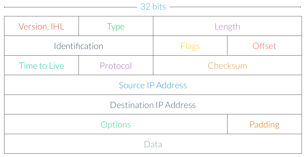
While TCP is concerned with segments, IP is instead concerned with datagrams, or packets. An IP packet, which is indeed similar to a TCP segment, looks like this:
Here are the key components of an IP packet:
-
Version and IHL. The version of IP being used to transfer data and the length of the headers.
-
Length. The total length of the packet.
-
Identification. In the event that a message is too large to fit into a single IP packet, this field is used to reconstruct data that has been broken up into separate chunks.
-
Flags. Similar to TCP flags, this section provides additional information about the type of the packet.
-
Time to Live. Often abbreviated TTL, the time to live field is the maximum number of hops this packet can make to its destination. Each time the packet passes through a router, the number in this field is decremented, and once it reaches zero, it is discarded by the router rather than being sent to its next destination.
-
Protocol. This field describes which protocol is being used to transmit the data. We’ve already seen how TCP works, and later, we’ll briefly look at UDP, another transfer protocol.
-
Header Checksum. The checksum is used for error checking and validation, just like the TCP checksum.
-
Source IP Address. The IP address from which the packet was sent.
-
Destination IP Address. The IP address the packet has been sent to.
-
Options. Using this field, a number of additional options can be specified.
-
Data. The actual data being transferred is found at the end of the packet.
Aha! There’s the IP address we couldn’t find last time. Notice also that IP doesn’t care about ports at all, since we saw that those are already handled by TCP.
Much of our discussion of TCP focused on dealing with the issues of lost or out-of-order segments. IP is actually at the root of both of these problems. While TCP ensures reliable data transfer, IP essentially gives us the opposite: best-effort delivery. Best-effort delivery says that a network will try its very hardest to deliver a message, but it doesn’t actually offer any guarantees that the message will reach its destination. The US Post Office, for example, operates using best-effort principles; you are not explicitly informed when your letter reaches its destination, and if the Post Office is overwhelmed with other letters, then the delivery of your letter could be delayed. Similarly, while we said that TCP was a connection-oriented protocol, IP, on the other hand, is connectionless. So, IP may deliver packets out of order, and packets may also be corrupted along the way. That’s why it’s so important for TCP to handle all of these errors!
Network Masks
It turns out that the IP addresses we’ve been looking for a while actually have some additional information encoded in them. Every IP address is divided into two parts: the network prefix and the host number. For example, the first 16 bits of an IP address might form the network prefix, while the latter 16 bits might be the host number. All computers on the same IP network will have the same network prefix, but each individual computer has a unique, identifying host number. In order to determine which part of an IP address is the network prefix and which is the host number, every IP network has a special number called a subnet mask. Subnet masks are commonly written as four octets separated by dots, just like an IP address.
Let’s look at an example. When determining an IP address’s network prefix and host number given the subnet mask of the network, it will actually be easier to think about IP addresses in binary. Didn’t think that would come back again, did you? Let’s say we have the IP address 192.168.56.50 on a network with a mask of 255.255.255.0. If we just convert the numbers between the dots into binary, we have an IP address of 11000000.10101000.00111000.00110010 and a mask of 11111111.11111111.11111111.00000000. Not too bad, right? To figure out the network prefix and the host number, let’s apply a binary AND operation to the IP address and the subnet mask. Remember, this just means that we’ll get a 1 if we AND together two 1s, and we’ll get a 0 otherwise. So, we have:
  11000000.10101000.00111000.00110010
& 11111111.11111111.11111111.00000000
-------------------------------------
  11000000.10101000.00111000.00000000
The result of this AND operation is the network prefix, which in this case, is 192.168.56.0. That must mean that the rest of the IP address is the host number, which in this case is 0.0.0.50. So, it looks like the first 24 bits of the IP address are used to determine the network, and then the last 8 bits are used to determine a computer on that network.
In that example, everything worked out kinda nicely because the network prefix and host number were separated by a dot. Let’s try a different subnet mask this time. We’ll use the same IP address 192.168.56.50, but with a subnet mask of 255.255.255.244. In binary, our subnet mask is 11111111.11111111.11111111.11100000. Let’s perform a binary AND, just like we did last time.
  11000000.10101000.00111000.00110010
& 11111111.11111111.11111111.11100000
-------------------------------------
  11000000.10101000.00111000.00100000
Okay, looks like we got a different number for the network prefix this time. Converting from binary to decimal, we get a network prefix of 192.168.56.32, which means we must have a host number of 00010010, or 18. This makes sense, though, since 32 + 18 = 50, which is the last quad in our IP address. So, using this subnet mask, we can create a network where all computers have the same network prefix (and different host numbers), but the network prefix and host number don’t necessarily have to be separated by one of the dots in an IP address.
It’s not really obvious from a subnet mask how many bits are used for the network prefix and how many bits are used for the host number, since we need to convert the mask to binary in order to figure that out. We could just memorize them all or get really good at math, but that seems to me like a waste of brain cells. Instead of telling people about the mask that’s associated with our network, we can instead use something called CIDR notation. CIDR notation is a bit more straightforward, since it just tells us how many bits of the IP address are used for the network prefix, from which we can infer how many bits are used for the host number. For example, the IP address 192.168.56.50 on a network with a mask of 255.255.255.0 would be written as 192.168.56.50/24 in CIDR notation. Here, the /24 simply says that 24 bits are used for the network prefix. From our second example, the mask 255.255.255.224 would correspond to /27 in CIDR notation (i.e., 192.168.56.50/27), since we’re using 27 bits for the network prefix.
Subnetworks
Using the network mask, we can also subdivide the computers on a network into different groups to keep them more organized and secure. For example, we might want to group together all the computers on the fifth floor of an office building into a subnetwork that is part of the building’s larger network. To introduce a new level of division, we can borrow a few bits from the IP address’s host number. So, rather than separating the IP address into two components, one that identifies the network and one that identifies the host, let’s divide it into three parts: one for the network prefix, one for the subnetwork identifier, and one for the host number.
Let’s take a look at an example. Our office building has network with a prefix of /24, and now we’d like to create four subnetworks. Normally, this prefix says that we should use 24 bits for the network prefix and 8 bits for the host number. But, let’s use some of the host number’s 8 bits to form a subnetwork identifier. How many bits will we need? Well, with two bits, we can represent four different numbers (00, 01, 10, and 11), so we’ll go ahead and borrow the first two bits from the host number to create a subnet identifier. With this change, we’ve created four subnetworks with a prefix of /26 from our original network with a prefix of /24.
Alright, let’s test this out: are the IP addresses 192.168.1.63/26 and 192.168.1.64/26 on the same subnetwork? Let’s convert these IP addresses to binary, since that seemed to work last time:
11000000.10101000.00000001.00111111
11000000.10101000.00000001.01000000
So, it looks like both of these IP addresses have the same /24 prefix but not the same /26 prefix, so these two are not on the same subnetwork. By the way, if we instead wanted up to eight different subnetworks from our original /24 network, we’d instead need to borrow three bits from the host number, which would create subnets with a prefix of /27 instead.
When choosing a subnet mask for a network, we’re also making a decision about the number of computers that can be on the same subnet. For example, a subnet mask of 255.255.255.0 (a prefix of /24), as we’ve seen, means that we have 8 bits available for the host number. Pulling out our binary skills again, the largest number we can represent with 8 bits is 28 = 255, so that’s how many different devices we can have on single subnet. On the other hand, if we choose a subnet mask of 255.255.255.224 (a prefix of /27), then we only get 5 bits for the host number, which means we can only have 32 devices on a single subnet. So, we have a bit of a trade-off: while we saw that a larger netmask will allow us to create more subnets, it also limits the number of devices that can be connected to the same subnet. This limitation is due to the fact that all IP addresses are the same size, so we only have so many bits to work with!
UDP
Many protocols on the Internet, most notably HTTP, use TCP/IP to send messages to other devices, but TCP isn’t the only way to send data across the net. UDP, or User Datagram Protocol, is commonly used by video chat applications like Skype or FaceTime. Unlike TCP, UDP does not guarantee that datagrams will actually be received by the client (which makes it a bit more similar to IP in that sense). However, in the case of video chat, for example, there are so many packets being sent in order to transfer your beautiful face to your friend’s computer that losing one of them doesn’t really make a difference at all. So, applications that are sending a whole lot of data over a network, such that nobody will really notice (or care) if tiny portions of it get lost, might want to use UDP instead of TCP, since there’s no need for a reliable connection. We’ve seen that TCP introduces a good amount of overhead to the data transfer process, which just might not be necessary for some applications. DNS queries, for example, use UDP for this reason, since it ends up being more efficient if we don’t have to take the time to make sure every single transmission was received successfully.
Five-Layer Internet Model
Before we finish up, let’s take a moment to step back and review some of the networking terms we’ve seen so far. As you’ve seen, we can organize the various networking protocols we’ve seen so far hierarchically. Here’s one way of doing so, called the Five-Layer Internet Model.
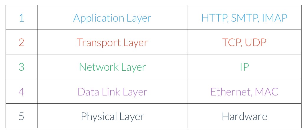
We’ll read this diagram from top to bottom; protocols at the top of the stack use protocols lower down the stack, so the layers get more and more fundamental.
-
Application Layer. The application layer, the highest level in our model, defines a set of standards that software applications can use to communicate. For example, a web browser and web server might communicate over HTTP, and an MUA and MDA might communicate using SMTP.
-
Transport Layer. The transport layer is concerned with delivering segments of information between two computers. Both TCP and UDP define standards for communicating between two hosts that are independent of the actual data being transferred.
-
Network Layer. The network layer defines a set of protocols to send packets through different networks. This layer handles giving computers on a network addresses as well as routing information to the right place.
-
Data Link Layer.
-
Physical Layer. Finally, there have to be some actual physical connections between devices. The physical layer refers both to the connections among the routers at the Internet’s core and the cable connecting to your modem at home!
And there you have it, the Internet! Phew, a whole lot goes into making those cat videos possible. In the next few sections, we’ll switch gears and talk all about multimedia: images, sound, and video!